


Status and crews
PUMP STATIONS, Status as of Jan. 1, 2024.
- PS 1, 4 and 9 operating.
- PS 5 operating as relief station.
- PS 3 on warm standby.
- PS 7 on warm standby, used in the winter to increase crude oil temperature.
- PS 2 ramped down July 1, 1997.
- PS 6 ramped down August 8, 1997.
- PS 8 ramped down June 30, 1996.
- PS 10 ramped down July 1, 1996. Demolished in 2019.
- PS 11 was not built, but has maintenance facilities.
- PS 12 ramped down April 1, 2005.
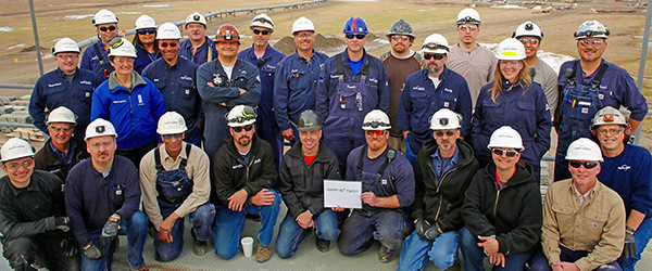
Crews: Crews vary per station; typically six to 25 employees. Personnel include security, maintenance, technicians, administrative professionals and safety employees. Shifts are generally one week on/one week off, or two weeks on/two weeks off.
Permanent Living Quarters: Permanent living quarters at PS 4, 5, 6 and 7. PS 1 personnel live in Deadhorse. PS 3 personnel typically live at PS 4. PS 9 personnel live in nearby communities.

E&A, Power
ELECTRIFICATION AND AUTOMATION (E&A): Electrification and Automation (also called “Strategic Reconfiguration” or “SR”) refers to Alyeska’s overall renewal of assets. Work began in 2001 and concentrated on reducing physical infrastructure and simplifying operations and maintenance. The project focused on creating more efficient operations while maintaining or enhancing safety, operational integrity and environmental performance. The system is modular and scalable and with flexibility for future increases or decreases in throughput.
As of March 2016, pump stations 1, 3, 4 and 9 were operating on new pumps; they have also been upgraded to use electrical (instead of diesel) power and are now automated [controlled remotely by Operations Control Center (OCC)]. Pump Stations 5 and 7 are using legacy equipment.
E&A upgrades include:
- Three new electrically driven mainline pump/ motor modules or MLUs at each station.
- Power generation modules at PS 1, 3 and 4 that include turbine drivers.
- Transmission line and substations for power supply from North Slope Central Power Facility at PS 1 and from GVEA at PS 9.
- Electrical distribution system and modules.
- Tie-ins and interconnecting crude oil and fuel gas piping and supports.
- Essential facilities for cold restart provided or maintained as appropriate.
- Upgraded relief control system actuators.
- Upgraded fire and gas systems.
- New onsite control, data gathering and data transfer systems.
- Upgraded pressure protection and process safety command system.
Power: All stations generate electrical power, with power plants ranging from 1.3 MW at PS 1 to 4.7 MW at PS 6, depending on availability of commercial power, presence of topping unit, and/or vapor recovery system. PS 8 and 9 also purchase commercial power.
Fuel Requirements: 30,000 to 60,000 gallons per day, average, per station (fuel oil equivalent).

Turbine engines, generators, pumps
PUMP STATIONS, Turbines: Turbine engines drive the pumps.
TURBINE GENERATORS, Electrical: PS 1 has one Siemens SGT 400 12.9 MW and one Rolls Royce 401KB7S 5 MW turbine generator. PS 3 and PS 4 each have two Siemens SGT 400 12.9 MW turbine generators. The units provide electricity to the station for essentials such as heat and lighting, as well as power for operation of the newer electrical pumps. At PS 1, both units are natural gas fired. At PS 3 and 4, one unit each is fired on natural gas only, while one unit each can be fired on natural gas or liquid (diesel) fuel. Liquid fuel is only used when the natural gas line is out of service. At PS 1, the SGT 400 is the normal turbine generator in service. The Rolls Royce–powered turbine generator is a backup, and Prudhoe-area grid power can be imported, if necessary. At PS 3 and 4, one unit at each station is normally in operation during summer months, and both units are normally in operation at each station during the winter months when pump recycle is being utilized.
The fuel consumption of a gas-fired Siemens SGT 400 is about 3.5 million standard cubic feet per day at full load. The fuel consumption for a liquid-fired unit operating near full load is about 20,000 gallons per day. A gas-fired Rolls Royce 501KB7S running at full load consumes approximately 1.7 million standard cubic feet per day.
PUMPS, Booster: All pump stations have booster pumps to move oil from the storage tanks to the mainline. (PS 1 has two mainline booster pumps to boost oil pressure.) PS 5 has two injection pumps.

Misc.
THROUGHPUT, Current Maximum Daily: 1.14 million barrels average (with four pump stations operating). Rates exceeding 750,000 barrels require addition of drag reducing agent (DRA).
PUMP STATIONS, Recirculation: In order to add heat to the crude oil, the oil is recirculated within the pump station. This results in additional heat being added to the crude before it leaves that pump station.
PUMP STATIONS, Refrigerated Foundations: PS 1, 3, 5 and 6.
Crude Oil Tank Capacity: PS 1: 420,000 barrels; PS 5: 150,000 barrels; all others: 55,000 barrels.
VALVES, Pump Stations and Terminal:
- Size: Two to 48 inches.
- Design pressure: Varies to meet process conditions. (Class 150# through Class 2500#.)
- Type: Gate, ball, check, plug, etc.
Fire Systems:
- Airfield rescue and fire training provided at stations with airports.
- Pump stations with airports have designated firefighting trucks for the airfields.
- Types: Halon, NOVAC, water and foam, dry chemical, wet chemical and carbon dioxide.